Multymeter.com â Electrical Engineering: It doesnât hurt to know a little about electrical installations, at least the installation for electronic goods installed in our own homes. The goal is to anticipate if there is an error, and we can immediately prevent it.
This image is an electrical diagram for the installation of a Split AC unit (Indoor and Outdoor), an electronic item that is commonly used every day.
Here is the explanation:
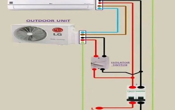
- Indoor Unit
- There is a cable connection terminal that connects the indoor unit to the outdoor unit using several colored cables: red, black, brown, blue, and green.
- This cable is used for the power source: Phase, neutral, and grounding.
2.Outdoor Unit
- Also has a terminal that is connected to the indoor unit with the appropriate cable.
- Functions as a compressor and condenser for the cooling system.
3.Isolator Switch
- Functions as a manual electric current breaker for AC maintenance or repair.
- Red cable: Phase
- Black cable: Neutral
Passes the isolator switch before going to the AC unit.
4. MCB (Miniature Circuit Breaker)
  â As a protector of electric current from short circuit or overload.
  â MCB is connected to the main power source, with the red cable as Phase (L) and the black cable as neutral (N).
5. Grounding (G â Green)
  â The green cable is used as a grounding system to avoid the risk of electric current leakage and increase safety.
This diagram shows how electricity flows from the power source through the MCB, isolator switch, then to the AC unit (indoor and outdoor), ensuring safe and efficient operation.***